Launch

Preparing the Faraday balloon payload for launch, Buttonwillow CA, August 2016
On the side of a desolate farmland road in Buttonwillow, CA on August 14, 2016 in mid-day 105°F heat, my brother Brent and I launched Faraday under a cluster of 15 party balloons, two of them Mylar for radar visibility, and a parachute. We built a simple 112 gram high-altitude balloon payload tasked with proving our system could be used in real-world missions with amateur radio. Brent had been President and I Vice-President of the RIT Amateur Radio Club, K2GXT, when it designed, built, and flew the RITCHIE-1 high altitude balloon in May 2011 to 96,305ft in upstate New York. RITCHIE-1 had been a four-pound regulated flight. Faraday came in at 112 grams, well under the FAR 101 threshold, by design.

The 112 gram Faraday payload ready for flight. Faraday board, GPS, antenna, and cut-down mechanism in a tupperware enclosure.
As SpaceX hardware engineers we followed the mantra “things that don’t have due dates don’t get done”. Hobby projects were not immune. RITCHIE-1 had taught us that balloon missions are an effective stress test of embedded design, system architecture, and mission planning. Setting a launch date helped prioritize our work on only what mattered for mission success: link budgets, telemetry parsing, mission sequences, and two-way communications.
For two and a half hours we followed the balloon in our chase car receiving 8,929 telemetry packets with a 10-mile link closure showing GPS altitude, velocity, and location. Faraday peaked at 31,795 feet altitude before a balloon popped causing a slow descent. We’d planned for this and included a failsafe timer to automatically cut the balloons away. Telemetry indicated that the burn wire drew high current but the cable did not sever: descent rate was unchanged. The payload was lost traveling East at 14,000 feet in the Tehachapi Mountains when it outran our ability to keep up with it. The cut-down burn wire was rudimentary; it should have been tested more if payload recovery was a priority.
Faraday worked so well on launch day because it was familiar. The project failed for the same reason.
What Faraday Aimed To Accomplish
Amateur radio defaulted to what was familiar: voice communications and cold-war era digital communications. In 2015 the most widely used digital network was still the 1200 baud automatic packet reporting system (APRS) developed by Bob Bruninga in the late 1980s. Many radio amateurs were interested in voice communications, and the prevailing digital advancement was D-STAR based on telephone-style communications. The hobby used new technology to recreate familiar capabilities.
Brent and I saw amateur radio uniquely positioned to excel at remote sensing and control. Build missions using the hobby as the medium. Rethink what the spectrum could do. We specifically sought to avoid attracting talkers to the project. We wanted builders to get excited. In 2014 three problems existed in the hobby: no 30kbps to 500kbps amateur radio oriented data hardware, no medium to high-speed data infrastructure to enable RF networking, and no consolidated educational resource for OSI level 2 and higher specific to the hobby to target the builders. We wanted to bring a new kind of person into the hobby.
Our target customers were 20s-30s engineering-oriented people who were interested in amateur radio for its experimental scene. We formed an Alpha users group of ten peers in six cities across the United States and conducted customer interviews in February 2015. From these discussions we realized we had to replace APRS which meant every user needed a GPS unit. Faraday had to have one onboard.
This was never intended to be a startup. It was a serious hobby project we held to professional standards because that was the only way either of us knew how to work. FaradayRF was set up as a Doing Business As (DBA) entity in California and we created a business plan, customer profiles, and product hypothesis. We were writing feature specifications after coming home from our day jobs at SpaceX designing hardware for Falcon 9 and Crew Dragon.
Architectural Decisions
We chose to base Faraday around the CC430 from Texas Instruments because Brent and I had familiarity from our time at the Rochester Institute of Technology with it. CC430 firmware was based on the MSP430 and thus was bare metal leaving Brent and me as the only developers. Of ten alpha testers and additional GitHub contributors, none crossed into feature work. Community building is hard; it’s harder when there is friction to contribution.
Most Faradays would ultimately be used attached to computer via USB as infrastructure, not battery operated. The low-power operation enabled remote missions out of the box. We dismissed this use-case’s impact on the requirements: bottlenecking feature development to the two of us for several years. We chose what we knew. That was a mistake.
Faraday Hardware Was Intentional
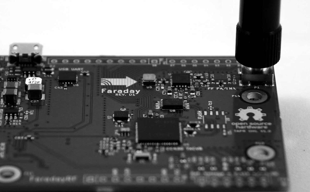
Faraday: CC430 microcontroller, RF chain, and SMA antenna connector.
The hardware was elegantly simple and manufacturable. It performed. The power architecture was based on USB 5V and external power up to 17V. An ideal diode cleanly transferred power between the higher voltage source. A DC/DC step-down converter based on the TPS562201 efficiently supplied the expected 500mA at 3.3V during transmissions. The microcontroller controlled a low-side MOSFET switch intended to complete the circuit for any load to ground. The MOSFET switch was paired on the connector with access to the external power rail as that would be the most convenient voltage rail for high-power loads. A pull-down resistor guaranteed OFF MOSFET state during power cycling when it’s possible the GPIO pin is high-impedance.
The CC430 implementation allocated eight GPIO pins, six 12-bit Analog to Digital Converter (ADC) pins, a button, and two LEDs for general use. ADCs were protected from overvoltage faults up to the maximum rated input voltage by limiting current into the internal ESD protection diodes. This was accomplished using the RC anti-aliasing filter series resistance. A simple method used in fault tolerant avionics that adds no cost. The ADC anti-aliasing filters were set at 16 Hz using available component values. ADC2 was unprotected to support external filtering.
Computers could communicate with the processor using the FTDI FT230XQ UART implemented with EMI/EMC filtering and ESD protection for data lines. The FTDI UART also leveraged ubiquitous Linux and Windows drivers for serial communications. The onboard real-time clock (RTC) and calendar features required a 32.768 KHz crystal. A 26 MHz system clock was used for more active operation. SRAM was baselined while FLASH memory was Do Not Populate (DNP) for future implementation: both implemented over Serial Peripheral Interface (SPI).
The Antenova M10478-A2 GPS receiver module took in 3.3V power and provided UART NMEA data sentences and a pulse per second. Combined with the real-time clock we were able to read in a GPS date and time, update the CC430 RTC registers, and save them on the PPS edge to provide reasonably accurate automated time and calendar services.
The RF chain was a simple CC430 differential RF output sent into a balun in an 0805 package that then passed through a SAW filter to provide additional filtering prior to amplification by the CC1190 RF front end up to 27dBm or 500mW. However, the SF2049E SAW filter used has a maximum insertion loss of 3.5dB which very likely accounts for the inability to hit full CC1190 output power due to drive strength. A tradeoff I made to prevent the transmitter from causing desensing of the GPS module operating at L1. The output of the CC1190 had additional filtering and antenna matching prior to the SMA connector leading to 50Ω coax or antenna. For receive, this path was largely reversed. All RF path capacitors were C0G/NPO to keep tight tolerances on performance over manufacturing and environmental conditions.
The PCB was designed for our intended manufacturer who was a startup called PCB:NG we met at the Hackaday Superconference 2016 in Pasadena, CA. We specifically used their 63 mil four-layer stackup for Faraday’s 2.95 inch by 2.1 inch PCB. Four layers is a sweet spot: it’s cheap but enables highly effective grounding architectures and EMI/EMC design approaches. Faraday was designed with Henry Ott’s “Partitioning and layout of a Mixed Signal PCB” which was an invaluable methodology for my professional work at SpaceX at the time designing 16-layer mixed signal PCBAs for Crew Dragon.
All required components were placed on the top side with only a single JTAG connector on the bottom we could quickly hand solder. All through-hole components, button, GPS module, and bottom JTAG connector were DNP as we planned to install them by hand. A choice which helped with product configurations and could be automated in the future.
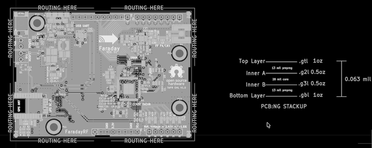
Faraday gerber layers with PCB:NG four-layer stackup. FaradayRF-Hardware
Manufacturable choices were a mindset. The PCB was designed to be tab route panelized with four mouse-bite areas indicated on each side allowing PCB:NG to quickly panelize with their proprietary method. Our gerbers clearly conveyed design intent with the routing path defined and notes indicating the routing area. We also embedded within the gerbers the intended stackup for clarity.
For RF routing on the top and bottom layers, I designed for our known stackup. The 25.6 mil wide 50Ω RF traces 13 mils above a ground plane with an FR4 dielectric constant of 3.8 results in a 48Ω trace. The beauty of engineering is that even with this mismatch we’d expect return loss to be less than that of the SMA connector in the design. Negligible. I’ll take that simplicity and move on. At 900 MHz, the free-space wavelength is about 33 cm, hence the 33cm amateur band. In FR4 with εr = 3.8, that wavelength shortens to roughly 6.3 inches. Traces start acting as transmission lines around 1/10th wavelength or longer. So any trace longer than 0.63 inches needs to be 50Ω transmission line; I kept the entire distance from SAW filter input to SMA connector at 1 inch.
The Antenova GPS module required copper pullback below its GPS antenna. All copper on all four layers below the GPS antenna area as defined by the datasheet were pulled back. The module was also intentionally placed on the opposite area of the board from the 900MHz RF circuitry isolating ground noise between the two high frequency systems. The GPS was quick to lock and reliable.
Production Hell
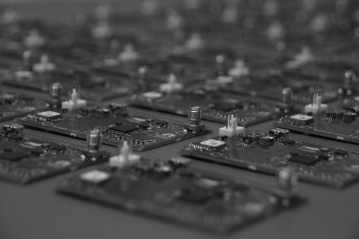
Faraday production batch, 109 units built across several runs
We entered production hell quickly. Not a single customer realized it. We built 109 Faraday units over several batches. The first 60 units had 23 boards with a functional error; a 38% failure rate and the issues appeared random. We received a second batch of 25 more units with 18 failing; a 72% failure rate and the issues were now more concentrated around the CC430 boot path. We extensively worked with PCB:NG to root cause and mitigate the issues: the second batch was traced to a consumable change made mid-run. Our last batch showed zero failures across units tested. Our production screening tests were working.
The Network Problem
A radio network with one user has zero value. 900MHz RF travels line of sight so geographical density mattered. The project would fail without a community communicating via RF. Our ten initial alpha testers were located in geographic hot-spots such as San Francisco, CA, Boston, MA, Los Angeles, CA, and Washington DC. Each alpha tester was asked to refer a local friend to the project. We could not let the initial users be located randomly around the country. We engineered the seed of the network.
Every radio was sold as a pair. Every user had at minimum a point-to-point link and any unit could become an APRS-IS gateway node. This guaranteed immediate utility. Store and forward operation was on the roadmap; until then, use was real-time.
The decision to use the CC430 was a major factor in failing to achieve escape velocity as a project. Lack of community contributions ultimately meant the project moved as fast as Brent and I could move. We had a mailing list with several hundred email addresses receiving weekly updates and a small FaradayRF Github community. The cost of converting someone into a contributor was incredibly high. Brent and I were the only feature contributors.
We joined startups in 2018. At SpaceX I could decide if spare time should go to a hobby project or my work. At Relativity Space it was unclear if I would be employed several months out. The project depended on two people carrying it forward. Choosing the CC430 was familiar in 2015 but fatal in 2018 when we had to move on.
Compounding Learning
I was the 17th employee and first Electrical Engineer at Relativity Space. The playbook that worked at SpaceX was irrelevant; the conditions were different. Rocketry in 2018 was hot; Astra Space, ABL, Virgin Orbit among others were fielding launch systems. One team failing to deliver by launch day meant no launch, regardless of everyone else. I didn’t want to fight head-on, I wanted asymmetric advantage. I knew other avionics teams would choose the familiar; I had experienced failure in comfort. I wasn’t sure I was right but I was sure the status quo was wrong.
Embedded computing had advanced between 2012 and 2018. ARM processors were ubiquitous. Accepting standard protocols’ shortcomings still closed mission needs: custom protocols were a resource sink. Multiple processors in each box were rational and unexpectedly allowed massive firmware reuse. I could not settle for a familiar avionics architecture.
Traditionally, tin whiskers are mitigated by defense in depth with leaded bulk solder, pre-tinning, BGA reballing, and conformal coating. The Arathane 5720 experiment from NASA showed no tin whiskers penetrating 2 mils of urethane conformal coating in 11 years. I challenged the assumption we had to mitigate tin whiskers given our risk profile: a tin whisker is the least of our worries on early flights of Terran 1. Seven years after pushing Relativity to be lead-free for Terran 1, Michael Pecht, the Director of the Center for Advanced Life Cycle Engineering at UMD confirmed my risk tolerance.
In aerospace Size, Weight, and Power (SWaP) is sacred. At SpaceX, a year-long effort to reduce avionics mass by several kilograms was erased in a single structures meeting. Avionics system mass was a fraction of structural dry-mass. I convinced Relativity Space to let me add mass to avionics early, simplify manufacturing, and remove variants: one box with one PCBA on Terran 1 replaced five boxes on Falcon 9 with multi-board backplanes. We negated the need for entire product teams as a result.
FaradayRF taught me that being uncertain doesn’t mean being silent, and familiar choices can still be wrong. It was unclear if FaradayRF would succeed; we did it anyway because amateur radio needed to change. Terran 1 needed to be different and an amateur radio project influenced my approach. We delivered Terran 1 avionics to the launch pad in five years with eight electrical engineers.